 少有人走的路
two_camera_calibration.hdev
* This example program shows how high precision mosaicking
* can be performed with calibrated cameras.
*
* Further information can be found in the
* Solution Guide III-C 3D Vision, Chapters 9 and 10.
* This example program is used in chapter 9 to
* illustrate calibrated mosaicking.
*
dev_update_off ()
ImgPath := '3d_machine_vision/multiple_cameras/'
*
* Open two windows for the left and the right image.
dev_close_window ()
read_image (Image1, ImgPath + 'camera1_ref')
get_image_size (Image1, Width, Height)
WindowScale := 0.66
dev_open_window (0, 0, Width * WindowScale, Height * WindowScale, 'black', WindowHandle1)
dev_open_window (0, Width * WindowScale + 6, Width * WindowScale, Height * WindowScale, 'black', WindowHandle2)
*
* Set some parameters for both windows.
dev_set_window (WindowHandle1)
dev_set_color ('green')
dev_set_draw ('margin')
dev_set_line_width (2)
dev_set_part (0, 0, Height - 1, Width - 1)
set_display_font (WindowHandle1, 16, 'mono', 'true', 'false')
*
dev_set_window (WindowHandle2)
dev_set_color ('green')
dev_set_draw ('margin')
dev_set_line_width (2)
dev_set_part (0, 0, Height - 1, Width - 1)
set_display_font (WindowHandle2, 16, 'mono', 'true', 'false')
*
* We assume that the two cameras are already calibrated
* (we know the internal camera parameters).
gen_cam_par_area_scan_division (0.01619, -734.789, 7.402e-006, 7.4e-006, 324.911, 256.894, 640, 480, CamParam1)
gen_cam_par_area_scan_division (0.0162584, -763.35, 7.39842e-006, 7.4e-006, 324.176, 245.371, 640, 480, CamParam2)
*
* Read the images and display them.
read_image (Image1, ImgPath + 'camera1_ref')
read_image (Image2, ImgPath + 'camera2_ref')
dev_set_window (WindowHandle1)
dev_display (Image1)
dev_set_window (WindowHandle2)
dev_display (Image2)
*
* Prepare the camera calibration.
CaltabName := 'caltab_30mm.descr'
create_calib_data ('calibration_object', 2, 1, CalibDataID)
set_calib_data_calib_object (CalibDataID, 0, CaltabName)
set_calib_data_cam_param (CalibDataID, 0, [], CamParam1)
set_calib_data_cam_param (CalibDataID, 1, [], CamParam2)
*
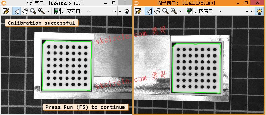
* Find and display the calibration plate in the images.
dev_set_window (WindowHandle1)
find_calib_object (Image1, CalibDataID, 0, 0, 0, [], [])
get_calib_data_observ_points (CalibDataID, 0, 0, 0, RowCoord1, ColumnCoord1, Index1, Pose1)
get_calib_data_observ_contours (Caltab1, CalibDataID, 'caltab', 0, 0, 0)
dev_display (Caltab1)
*
dev_set_window (WindowHandle2)
find_calib_object (Image2, CalibDataID, 1, 0, 0, [], [])
get_calib_data_observ_points (CalibDataID, 1, 0, 0, RowCoord2, ColumnCoord2, Index2, Pose2)
get_calib_data_observ_contours (Caltab2, CalibDataID, 'caltab', 1, 0, 0)
dev_display (Caltab2)
*
disp_message (WindowHandle1, 'Calibration successful', 'window', 12, 12, 'black', 'true')
disp_continue_message (WindowHandle1, 'black', 'true')
stop ()
clear_calib_data (CalibDataID)
*
* Determine the offset between the calibration plate surface
* and the object surface
ThicknessCaliper := 2.9 / 1000.0
ThicknessPlate := 5.65 / 1000.0
DiffHeight := ThicknessPlate - ThicknessCaliper
DistancePlates := 0.06488
*
* Define the pixel size of the mosaic image (in meters).
PixelSize := 0.0001
*
* For the first (left) image, the determination
* of the necessary shift of the pose is straightforward.
* You can define the upper left corner of the rectified image
* in image coordinates
* based on a preselected border width.
BorderInPercent := 7
get_image_size (Image1, WidthImage1, HeightImage1)
UpperRow := HeightImage1 * BorderInPercent / 100.0
LeftColumn := WidthImage1 * BorderInPercent / 100.0
*
* Then, this point must be transformed into world coordinates.
image_points_to_world_plane (CamParam1, Pose1, UpperRow, LeftColumn, 'm', LeftX, UpperY)
*
* For the determination of the height of the rectified image
* we need to define a point that lies near the lower border
* of the first image.
LowerRow := HeightImage1 * (100 - BorderInPercent) / 100.0
*
* Again, this point must be transformed
* into the world coordinate system.
image_points_to_world_plane (CamParam1, Pose1, LowerRow, LeftColumn, 'm', X1, LowerY)
*
* The height can be determined as the vertical distance
* between the upper left point and the point near the
* lower image border, expressed in pixels of the rectified image.
HeightRect := int((LowerY - UpperY) / PixelSize)
*
* Analogously, the width can be determined from a point t
* hat lies in the overlapping area of the two images,
* i.e., near the right border of the first image.
OverlapInPercent := 20
RightColumn := WidthImage1 * (100 - OverlapInPercent / 2.0) / 100.0
image_points_to_world_plane (CamParam1, Pose1, UpperRow, RightColumn, 'm', RightX, Y1)
WidthRect := int((RightX - LeftX) / PixelSize)
*
* With the shifted pose and the size of the rectified image,
* the rectification map for the first image can be derived.
set_origin_pose (Pose1, LeftX, UpperY, DiffHeight, PoseNewOrigin1)
gen_image_to_world_plane_map (MapSingle1, CamParam1, PoseNewOrigin1, Width, Height, WidthRect, HeightRect, PixelSize, 'bilinear')
*
* Generate a new homogeneous transformation matrix.
hom_mat3d_identity (HomMat3DIdentity)
*
* The second image must be rectified such that it fits exactly
* to the right of the first rectified image. This means that the
* upper left corner of the second rectified image must be identical
* with the upper right corner of the first rectified image.
* Therefore, we need to know the coordinates of the upper right corner
* of the first rectified image in the coordinate system that is defined
* by the calibration plate in the second image.
* First, we express the upper right corner of the first rectified image
* in the world coordinate system that is defined by the calibration plate
* in the first image. It can be determined by a transformation from
* the origin into the upper left corner of the
* first rectified image (a translation) followed by a translation along
* the upper border of the first rectified image. Together with the shift
* that compensates the thickness of the calibration plate, this
* transformation is represented by the homogeneous transformation matrix:
hom_mat3d_translate_local (HomMat3DIdentity, LeftX + PixelSize * WidthRect, UpperY, DiffHeight, cp1Hur1)
hom_mat3d_translate_local (HomMat3DIdentity, DistancePlates, 0, 0, cp1Hcp2)
*
* Then, we need the transformation between the two calibration plates of
* the calibration object. The homogeneous transformation matrix cp1Hcp2
* describes how the world coordinate system defined by the calibration plate
* in the first image is transformed into the world coordinate system
* defined by the calibration plate in the second image. This transformation
* must be known beforehand from a precise measurement of the calibration object.
* From these two transformations, it is easy to derive
* the transformation that transforms the world coordinate system
* of the second image such that its origin lies in the upper left corner
* of the second rectified image. For this, the two transformations
* have to be combined appropriately.
hom_mat3d_invert (cp1Hcp2, cp2Hcp1)
hom_mat3d_compose (cp2Hcp1, cp1Hur1, cp2Hul2)
*
* With this, the pose of the calibration plate in the second image
* can be modified such that the origin of the world coordinate system
* lies in the upper left corner of the second rectified image.
pose_to_hom_mat3d (Pose2, cam2Hcp2)
hom_mat3d_compose (cam2Hcp2, cp2Hul2, cam2Hul2)
hom_mat3d_to_pose (cam2Hul2, PoseNewOrigin2)
*
* With the resulting new pose and the size of the rectified image,
* which can be the same as for the first rectified image,
* the rectification map for the second image can be derived.
gen_image_to_world_plane_map (MapSingle2, CamParam2, PoseNewOrigin2, Width, Height, WidthRect, HeightRect, PixelSize, 'bilinear')
*
* Open a new Graphics Window for the merged image.
dev_open_window (Height * WindowScale, 0, Width * 2 * WindowScale, Height * WindowScale, 'black', WindowHandleCombined)
set_display_font (WindowHandleCombined, 16, 'mono', 'true', 'false')
dev_set_color ('green')
dev_set_draw ('margin')
ScalePlot := 200
RowPlot := 400
Coord := [0:2000]
*
* Process all image pairs in a loop.
for I := 1 to 3 by 1
*
* Display both images.
dev_set_window (WindowHandle1)
read_image (Image1, ImgPath + 'camera1_' + I$'02d')
get_image_size (Image1, WidthImage1, HeightImage1)
dev_set_part (0, 0, HeightImage1 - 1, WidthImage1 - 1)
dev_display (Image1)
dev_set_window (WindowHandle2)
read_image (Image2, ImgPath + 'camera2_' + I$'02d')
get_image_size (Image2, WidthImage2, HeightImage2)
dev_set_part (0, 0, HeightImage2 - 1, WidthImage2 - 1)
dev_display (Image2)
*
* Start the time measurement.
count_seconds (TimeStart1)
*
* Rectify the image pair from the two-camera setup with map_image.
map_image (Image1, MapSingle1, RectifiedImage1)
map_image (Image2, MapSingle2, RectifiedImage2)
concat_obj (RectifiedImage1, RectifiedImage2, Concat)
* End the time measurement and calculate the difference.
count_seconds (TimeEnd1)
Time1 := TimeEnd1 - TimeStart1
*
dev_set_window (WindowHandleCombined)
* Start the time measurement again.
count_seconds (TimeStart2)
*
* Tile both images into one large image.
tile_images (Concat, Combined, 2, 'vertical')
*
* End the time measurement again and calculate the difference.
count_seconds (TimeEnd2)
Time2 := TimeEnd2 - TimeStart2
*
* Display the combined image and the time measurement.
get_image_size (Combined, WidthComb, HeightComb)
dev_set_part (0, 0, HeightComb - 1, WidthComb - 1)
dev_display (Combined)
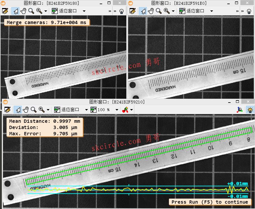
disp_message (WindowHandle1, 'Merge cameras: ' + (1000 * (Time1 + Time2))$'.3' + ' ms', 'window', 12, 12, 'black', 'true')
*
* In addition, we plot the accuracy of the mosaicking with a procedure.
plot_mosaicking_accuracy (Combined, WidthRect, HeightRect, WindowHandleCombined, Coord, ScalePlot, RowPlot)
if (I < 3)
disp_continue_message (WindowHandleCombined, 'black', 'true')
stop ()
endif
endfor本文出自勇哥的网站《少有人走的路》wwww.skcircle.com,转载请注明出处!讨论可扫码加群:


")
")
常用的6种方法")
 封装运动功能")
:与C#不同点,鸭子类型,多线程,多进程编程,访问控制,事件委托实现,lambda表达式,常用内置库,为啥说python简单易用?")


:安装模块,验证模块是否正常,一个简单的gui测试")
")
Qt Widgets Designer界面设计器和界面应用")
:有无数组?字符串方法,读写文件,序列化,配置文件,异常处理,循环和选择,模块与包,调试手段")
:枚举,装饰器,self,类的三种类型,特殊方法,oop,代码格式,方法 ,方法返回类型,识别函数返回类型")