 少有人走的路
2.1 the process of 1D Edge extraction
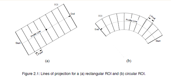
Then, the mean gray value along each line of projection is calculated. The sequence of these mean values
is called the profile简单的说 是以 profile Line 为基准 对profile Line 垂直方向上的 灰度值取平均。这一系列的平均灰度值组成profile。
如果以profile Line 为基准,它的垂线不是 水平或者数值的时候 如上图 (a)(b) ,就需要一个插值操作。目前halcon支持的有'nearest_neighbor', 'bilinear', 'bicubic' 。就如同我们对一副图像进行缩放或者旋转的时候为了尽可能的保证处理后的图像保持原来的细节需要进行插值一样。
我们用测量助手的时候 其中有一个轮廓线的呈现,就是平均灰度值组成的结果。
如下图:
现在以gen_measure_rectangle2( : : Row, Column, Phi, Length1, Length2, Width, Height, Interpolation : MeasureHandle) 为例说明各参数作用。
ROW : 测量矩形的Y 中心
COL: 测量矩形的X中心
PHI: 测量矩形旋转角度
Len1,Len2:测量矩形宽高的一半
Width,Height:图像宽高
Interpolation:插值类型
MeasrueHandle:测量句柄
关于 测量ROI宽度的选择,如果测量的边缘和profile line 是垂直关系,则宽度尽肯能的宽 这样可以减少噪声.
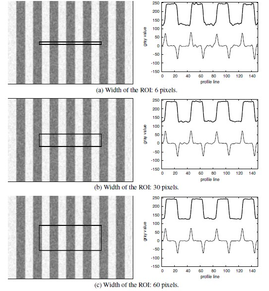
如果测量的边缘和profileline 不是垂直的关系 则宽度要尽可能的小,相应的噪声增加。
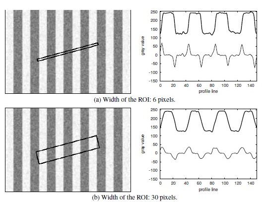
综上所述 在ID 测量的时候 最好 将 profile Line 与待测边缘垂直 而且尽可能的宽 以减少噪声。
如果不能保持垂直 那么 ROI的宽度要尽可能小。
2.2 create a measure object
gen_measure_rectangle2
gen_measure_arc.
2.3 using the measure object
measure_pairs(Image : : MeasureHandle, Sigma, Threshold, Transition, Select : RowEdgeFirst, ColumnEdgeFirst, AmplitudeFirst,RowEdgeSecond, ColumnEdgeSecond, AmplitudeSecond, IntraDistance, InterDistance)
在用measure_pair 进行测量之前 有必要了解一下halcon的measure_pair 是怎么工作的。
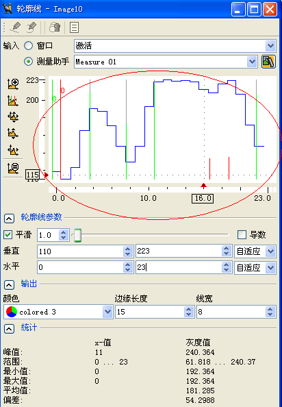
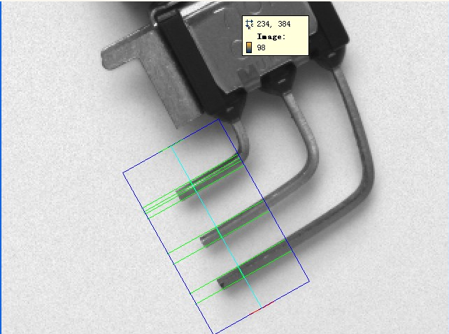
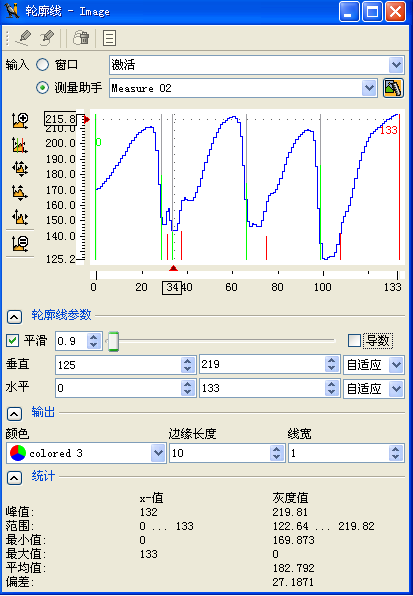
上四副图是halcon的测量助手的截图。
图1是设定的ROI区域
图3 中是灰度均值组成的连续曲线 需要说明的是 图中 最多边和最右边的两条红线是参看线 中间的4组蓝红线才是符合条件的边缘线
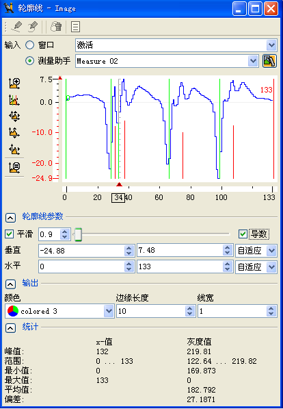
图4 是图3的一阶导数 需要说明的是 图中 最多边和最右边的两条红线是参看线 中间的4组蓝红线才是符合条件的边缘线
图2 是各种参数的设置
【最小边缘幅度】= 10 对应measure_pairs中的【threshold】参数 从图4可以看到 图中留下的红蓝线的绝对值都是大于等于10的
【平滑】=0.9 对应 measure_pairs中的【sigma】参数
勾选后为'all_strongest', 'positive_strongest', 'negative_strongest'
'positive': only negative edges, i.e., light-to-dark 只返回负梯度值的边缘,图4中蓝线所示
'negative' :相反。
'all' : 返回的是 正负都有
【位置】all 选择所有 first 选择第一组/条 last 选择最后一组/条
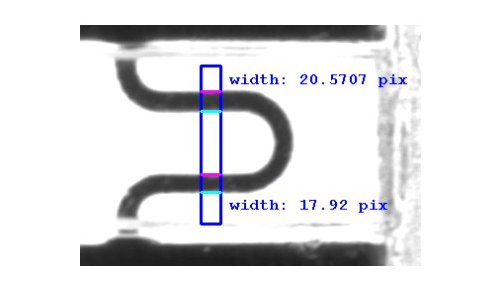
boundary一个例子:测保险丝的宽度 Example: solution_guide/basics/fuse.hdev
**********************************************
* 思路:1.gen_measure_rectangle2 创建测量区域
2.measure_pairs 配对
3.显示结果
****************************************************
read_image(Fuse,'fuse')
get_image_size(Fuse,Width,Height)
Row := 297
Column := 545
Lenght1 :=80
Lenght2 :=10
get_image_size(Fuse,Width,Height)
Row := 297
Column := 545
Lenght1 :=80
Lenght2 :=10
* 旋转90度
Angle :=rad(90)
*Length1 为矩形宽 Length2为矩形高
Angle :=rad(90)
*Length1 为矩形宽 Length2为矩形高
gen_measure_rectangle2(Row,Column,Angle,Lenght1,Lenght2,Width,Height,\
'bilinear',MeasureHandle)
'bilinear',MeasureHandle)
* 对图像的测量区域配对
* 如上实验图为两对直线
*配对后的中心坐标存放在RowEdgeFirst,\
* ColumnEdgeFirst,\
* ColumnEdgeFirst,\
* RowEdgeSecond,\
* ColumEdgeSecond 数组中
* ColumEdgeSecond 数组中
*每对线- 两条线的距离在 IntraDistance 数组中
measure_pairs(Fuse,MeasureHandle,1,1,'negative','all',RowEdgeFirst,\
ColumnEdgeFirst,AmpliudeFirst,RowEdgeSecond,\
ColumEdgeSecond,AmpliudeSecond,IntraDistance,\
InterDistance)
ColumnEdgeFirst,AmpliudeFirst,RowEdgeSecond,\
ColumEdgeSecond,AmpliudeSecond,IntraDistance,\
InterDistance)
*得到线 如实验图所示
*measure_pairs 得到的只是点现在 计算出线
*gen_contour_polygon_xld(Edge,[0,1,2,2,2],[0,0,0,1,2]) 可以得到这样的图形
*gen_contour_polygon_xld(Edge,[0,1,2,2,2],[0,0,0,1,2]) 可以得到这样的图形
* |
* |
* |————
* 左下 以坐上角(0,0)为原点
for i :=0 to | RowEdgeFirst |-1 by 1
gen_contour_polygon_xld (EdgeFirst, \
[-sin(Angle+rad(90))*Lenght2+RowEdgeFirst[i],\
-sin(Angle-rad(90))*Lenght2+RowEdgeFirst[i]],\
[cos(Angle+rad(90))*Lenght2+ColumnEdgeFirst[i], \
cos(Angle-rad(90))*Lenght2+ColumnEdgeFirst[i]])
gen_contour_polygon_xld (EdgeSecond, \
[-sin(Angle+rad(90))*Lenght2+RowEdgeSecond[i],\
-sin(Angle-rad(90))*Lenght2+RowEdgeSecond[i]],\
[cos(Angle+rad(90))*Lenght2+ColumEdgeSecond[i], \
cos(Angle-rad(90))*Lenght2+ColumEdgeSecond[i]])
dev_set_color ('cyan')
dev_display (EdgeFirst)
dev_set_color ('magenta')
dev_display (EdgeSecond)
dev_set_color ('blue')
endfor
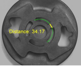
一个例子: 检测铸造零件 Example: hdevelop/Applications/Measuring-2D/measure_arc.hdev
******************************
*measure_pos
*思路:先生成一个圆弧,即弧线上的点作为测量区域
* 用measure_pos测量弧线的点得出 孔间距离
************************************
read_image(Zeiss1,'zeiss1')
get_image_size(Zeiss1,Width,Height)
dev_close_window()
dev_open_window(0,0,Width/2,Height/2,'black',WindowHandle)
dev_display(Zeiss1)
Row := 275
Column :=335
Radius :=107
AngleStart :=-rad(55)
AngleExtent :=rad(170)
*获取椭圆指定角度的点坐标
get_points_ellipse(AngleStart+AngleExtent,Row,Column,0,Radius,Radius,\
RowPoint,ColPoint )
dev_set_draw('fill')
dev_set_color('green')
dev_set_line_width(1)
*显示圆
disp_arc (WindowHandle, Row, Column, AngleExtent,RowPoint, ColPoint)
*生成测量圆弧
gen_measure_arc(Row,Column,Radius,AngleStart,AngleExtent,10,\
Width,Height,'nearest_neighbor',MeasureHandle)
*测量
measure_pos(Zeiss1,MeasureHandle,1,10,'all','all',RowEdge,\
ColumnEdge,Amplitude,Distance)
*计算距离
distance_pp(RowEdge[1],ColumnEdge[1],RowEdge[2],ColumnEdge[2],IntermeDist)
dev_set_color('red')
dev_set_line_width(3)
disp_line(WindowHandle,RowEdge[1],ColumnEdge[1],RowEdge[2],ColumnEdge[2])
disp_message(WindowHandle,'Distance: ' + IntermeDist , 'image',\
250,8,'yellow','false')
close_measure(MeasureHandle)
例子:Fuzzy Measuring Example: hdevelop/Applications/Measuring-2D/fuzzy_measure_pin.hdev
没看懂
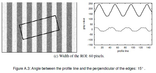
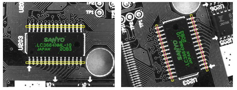
例子:Measuring Leads of a Moving IC 测量电路板的针脚边缘
例子:Measuring Leads of a Moving IC 测量电路板的针脚边缘
**************************************************************
* *对于角度,不可以这样:比如 AngleStart :=350 AngleExtent :=20,这样到360就会停止,而应该是这样AngleStart:=-10
* Optimization, *这个用于优化生成模型的 点 尤其是对于比较大的图像, If Optimization = 'none', all model points are stored ,其他未知
* Metric, *If Metric = 'use_polarity', the object in the image and the model must have the same contrast. If, for example, the model is a bright * *object on a dark background, the object is found only if it is also brighter than the background.
*
*
* inspect_shape_model(Image : * 输入 -- 建模的图片
* ModelImages, * 输出 --金子塔图片 如果NumLevels = 4 那就是四张哦
* ModelRegions : *输出 --二值后的模型
* NumLevels, * 输入 -- 金字塔等级
* Contrast : ) * 二值化阈值
* find_shape_model(Image : : ModelID, AngleStart, AngleExtent,
* MinScore, * 最小相似度 如 0.7 则要 70%相似
* NumMatches, *
* MaxOverlap, *如果模型是一个 对称的模型 ,那么在找模型的时候 可能会有重叠的区域 哦说不清楚额[0.0,1.0]
* SubPixel,
* NumLevels, * 金字塔数 可选值: 0, 1, 2, 3, 4, 5, 6, 7, 8, 9, 10
* Greediness : * of the search heuristic (0: safe but slow; 1: fast but matches may be missed
*
* 思路:以芯片的字母区域做基准, 用模型匹配来校准 测量区域
*
**********************************************************
dev_update_pc('off')
dev_update_window('off')
dev_update_var('off')
open_framegrabber ('File', 1, 1, 0, 0, 0, 0, 'default', -1, \
'default', 'default', 'default', 'board/board.seq', 'default',\
-1, -1, FGHandle)
grab_image(Image,FGHandle)
get_image_size(Image,Width,Height)
dev_close_window()
dev_open_window(0,0,Width,Height,'black',WindowHandle)
dev_set_window(WindowHandle)
dev_display(Image)
Row1 :=188
Column1 :=182
Row2 :=298
Column2 :=412
gen_rectangle1(Rectangle,Row1,Column1,Row2,Column2)
area_center(Rectangle,Area,Row,Column)
dev_display(Rectangle)
Rect1Row :=-102
Rect1Col :=5
Rect2Row :=107
Rect2Col :=5
RectPhi :=0
RectLength1 :=170
RectLength2 :=5
gen_rectangle2 (Rectangle1, Row+Rect1Row, Column+Rect1Col, RectPhi, RectLength1, RectLength2)
gen_rectangle2 (Rectangle2, Row+Rect2Row, Column+Rect2Col, RectPhi, RectLength1, RectLength2)
dev_display(Rectangle1)
dev_display(Rectangle2)
*创建模型
reduce_domain(Image,Rectangle,ImageReduced)
create_shape_model (ImageReduced,'auto', 0, rad(360), rad(1), 'none', 'use_polarity', 30, 'auto', ModelID)
*获取模型轮廓 shapeModel 在下面有用到哦
*shapeMode 是基准 ,这里shapemodel 的中心点 是原点(0,0) 也就是图像的左上角
get_shape_model_contours(ShapeModel,ModelID,1)
*这段代码没用 囧 ~~ 例子里写这段干嘛 不嫌长啊
*
*创建变换矩阵
*hom_mat2d_identity(HomMat2DIndentity)
*平移矩阵
*hom_mat2d_translate(HomMat2DIndentity,Row,Column,HomMat2DTranslate)
*shapeModel平移 ,这样就到了原来的位置
*因为没有旋转,所以不需要旋转变换了
*affine_trans_contour_xld(ShapeModel,ShapeMOdelTrans,HomMat2DTranslate)
disp_message(WindowHandle,['Press left button to start','and stop the demo'],\
'image',12,12,'black','true')
get_mbutton(WindowHandle,Row3,Column3,Button1)
Button :=0
while(Button #1)
dev_set_window(WindowHandle)
dev_set_part(0,0,Height-1,Width-1)
grab_image(ImageCheck,FGHandle)
dev_display(ImageCheck)
*得到匹配模型的位置和旋转角度
find_shape_model (ImageCheck, ModelID, rad(0), rad(360), 0.7, 1, 0.5, 'least_squares', 4, 0.7,\
RowCheck, ColumnCheck, AngleCheck, Score)
if(|Score| > 0)
dev_set_color('green')
*这里对shapeModel(基准shapemodel 是在图像原点的) 做平移和旋转操作.
hom_mat2d_identity(HomMat2DIndentity)
hom_mat2d_translate(HomMat2DIndentity,RowCheck,ColumnCheck,HomMat2DTranslate)
hom_mat2d_rotate(HomMat2DTranslate,AngleCheck,RowCheck,ColumnCheck,HomMat2DRotate)
affine_trans_contour_xld(ShapeModel,ShapeModelTrans,HomMat2DRotate)
dev_display(ShapeModelTrans)
*这里是对测量区域做校准,图像变换后,测量区域也是要跟着变的饿
*根据新的变换矩阵,以 测量区域 Rect1Row等 求出变换后的 新Rect1RowCheck
*这样就可以创建新的 测量区域了
affine_trans_pixel(HomMat2DRotate,Rect1Row,Rect1Col,Rect1RowCheck,Rect1ColCheck)
affine_trans_pixel(HomMat2DRotate,Rect2Row,Rect2Col,Rect2RowCheck,Rect2ColCheck)
gen_rectangle2(Rectangle1Check,Rect1RowCheck,Rect1ColCheck,AngleCheck,RectLength1,RectLength2)
gen_rectangle2(Rectangle2Check,Rect2RowCheck,Rect2ColCheck,AngleCheck,RectLength1,RectLength2)
dev_set_color('blue')
dev_set_draw('margin')
dev_set_line_width(3)
dev_display(Rectangle1Check)
dev_display(Rectangle2Check)
gen_measure_rectangle2 (Rect1RowCheck, Rect1ColCheck, AngleCheck, RectLength1, RectLength2,\
Width, Height, 'nearest_neighbor', MeasureHandle1)
gen_measure_rectangle2 (Rect2RowCheck, Rect2ColCheck, AngleCheck, RectLength1, RectLength2,\
Width, Height, 'nearest_neighbor', MeasureHandle2)
measure_pairs (ImageCheck, MeasureHandle1, 2, 90, 'positive', 'all', RowEdgeFirst1, \
ColumnEdgeFirst1, AmplitudeFirst1, RowEdgeSecond1, ColumnEdgeSecond1, AmplitudeSecond1, IntraDistance1, InterDistance1)
measure_pairs (ImageCheck, MeasureHandle2, 2, 90, 'positive', 'all', RowEdgeFirst2, \
ColumnEdgeFirst2, AmplitudeFirst2, RowEdgeSecond2, ColumnEdgeSecond2, AmplitudeSecond2, IntraDistance2, InterDistance2)
close_measure(MeasureHandle1)
close_measure(MeasureHandle2)
dev_set_color('red')
dev_set_draw('fill')
disp_line (WindowHandle, RowEdgeFirst1-RectLength2*cos(AngleCheck), ColumnEdgeFirst1-RectLength2*sin(AngleCheck), RowEdgeFirst1+RectLength2*cos(AngleCheck), ColumnEdgeFirst1+RectLength2*sin(AngleCheck))
disp_line (WindowHandle, RowEdgeSecond1-RectLength2*cos(AngleCheck), ColumnEdgeSecond1-RectLength2*sin(AngleCheck), RowEdgeSecond1+RectLength2*cos(AngleCheck), ColumnEdgeSecond1+RectLength2*sin(AngleCheck))
disp_line (WindowHandle, RowEdgeFirst2-RectLength2*cos(AngleCheck), ColumnEdgeFirst2-RectLength2*sin(AngleCheck), RowEdgeFirst2+RectLength2*cos(AngleCheck), ColumnEdgeFirst2+RectLength2*sin(AngleCheck))
disp_line (WindowHandle, RowEdgeSecond2-RectLength2*cos(AngleCheck), ColumnEdgeSecond2-RectLength2*sin(AngleCheck), RowEdgeSecond2+RectLength2*cos(AngleCheck), ColumnEdgeSecond2+RectLength2*sin(AngleCheck))
wait_seconds(2)
endif
* get_mposition (WindowHandle, R, C, Button)
endwhile
例子:Inspect IC Example: hdevelop/Applications/Measuring-2D/measure_pin.hdev
图0
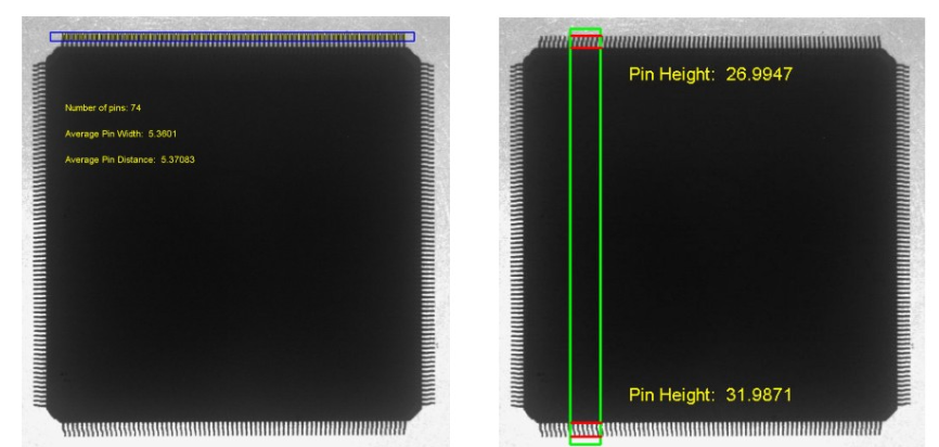
图1 :sigma = 1.0
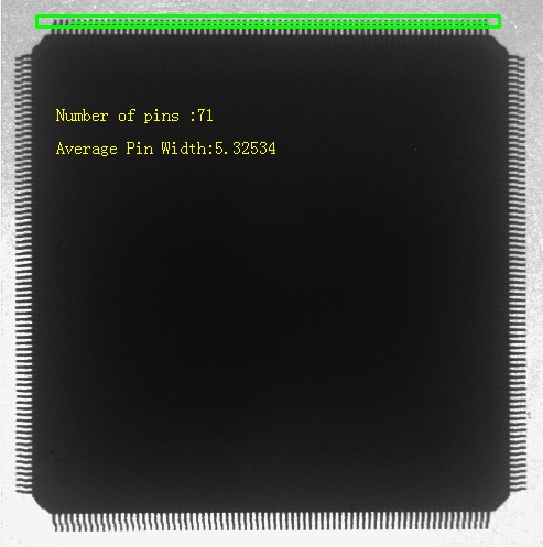
图2 sigma=1.5
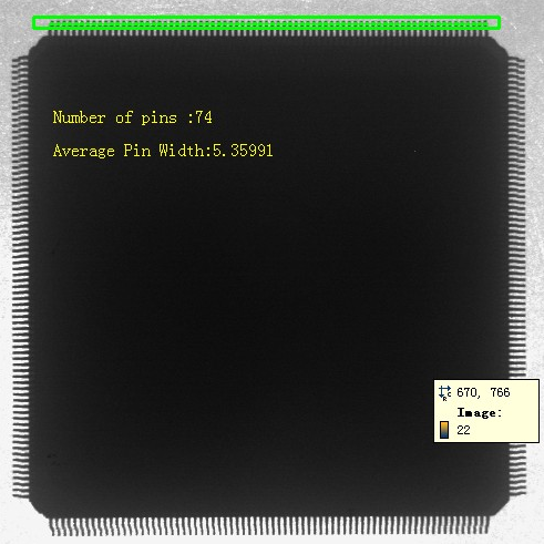
图3 sigma =3.0

*************************************************************
*
*①测量针脚个数,宽度,间距
*②测量针脚长度
*measure_pairs 与 measure_pos 的不同
*在此例子中 meausre_pairs 用于检测针脚宽度 measure_pos 用于检测阵脚高度
* measure_pairs 适用于处理用边缘包围的物体,如针脚宽度,中间有白色区域将每个针脚隔开,而且可以根据Transition参数将得到不同的测量结果,
* 如阵脚两侧的边缘点(这些点是图0左红线的中心点) 结果返回在RowEdgeFirst, ColumnEdgeFirst,RowEdgeSecond, ColumnEdgeSecond 数* 组中
* 而遇到图0右 中测量针脚高度的时候 就可以用measure_pos
* Transition, *List of values: 'all', 'positive', 'negative', 'all_strongest', 'positive_strongest', 'negative_strongest'
* *参数含义见说明文档
* ,AmplitudeSecond,
* IntraDistance, *在此例子中是针脚宽度的数组
* InterDistance) *在此例子中是 针脚间的间距
*
*
* measure_pos(Image : : MeasureHandle, Sigma, Threshold, Transition, Select : RowEdge, ColumnEdge, Amplitude,
* Distance) * 在此例子中是图0右边四条红线的间距,即有三个间距。
****************************************************************
dev_close_window()
read_image(Image,'ic_pin')
get_image_size(Image,Width,Height)
dev_open_window(0,0,Width/2,Height/2,'black',WindowHandle)
dev_display(Image)
Row :=47
Column :=485
Phi :=0
Length1 :=420
Length2 :=10
dev_set_color('green')
dev_set_draw('margin')
dev_set_line_width(3)
gen_rectangle2(Rectangle,Row,Column,Phi,Length1,Length2)
gen_measure_rectangle2(Row,Column,Phi,Length1,Length2,Width,Height,\
'nearest_neighbor',MeaserHandle)
* If Transition = 'negative', the edge points with a light-to-dark transition
*in the direction of the major axis of the rectangle are returned in RowEdgeFirst
*and ColumnEdgeFirst. In this case, the corresponding edges with a drak-to-light
*transition are returned in RowEdgeSecond and ColumnEdgeSecond
*sigma 参数效果如上图1,2所示
measure_pairs (Image, MeaserHandle, 1.5, 30, 'negative', 'all', RowEdgeFirst,\
ColumnEdgeFirst, AmplitudeFirst, RowEdgeSecond, ColumnEdgeSecond,\
AmplitudeSecond, PinWidth, PinDistance)
disp_line (WindowHandle, RowEdgeFirst, ColumnEdgeFirst, RowEdgeSecond,\
ColumnEdgeSecond)
avgPinWidth :=sum(PinWidth)/|PinWidth|
avgPinDistance :=sum(PinDistance)/|PinDistance|
numPins :=|PinWidth|
dev_set_color('yellow')
disp_message(WindowHandle,'Number of pins :'+numPins,'image',200,100,'yellow','false')
disp_message(WindowHandle,'Average Pin Width:' +avgPinWidth,'image',260,100,'yellow','false')
*来个特写
stop()
Row1 := 0
Column1 := 600
Row2 := 100
Column2 := 700
dev_set_color ('blue')
disp_rectangle1 (WindowHandle, Row1, Column1, Row2, Column2)
dev_set_part(Row1,Column1,Row2,Column2)
dev_display(Image)
dev_set_color('green')
dev_display(Rectangle)
dev_set_color('red')
disp_line (WindowHandle, RowEdgeFirst, ColumnEdgeFirst, RowEdgeSecond,\
ColumnEdgeSecond)
close_measure(MeaserHandle)
stop()
dev_set_part(0,0,Height-1,Width-1)
dev_display(Image)
dev_set_line_width(3)
Row := 508
Column := 200
Phi := -rad(90)
Length1 := 482
Length2 := 35
gen_rectangle2 (Rectangle, Row, Column, Phi, Length1, Length2)
gen_measure_rectangle2 (Row, Column, Phi, Length1, Length2, Width, Height, 'nearest_neighbor', MeasureHandle)
measure_pos (Image, MeasureHandle, 1.5, 30, 'all', 'all', RowEdge, ColumnEdge, Amplitude, Distance)
disp_line(WindowHandle,RowEdge,ColumnEdge-Length2,RowEdge,ColumnEdge+Length2)
PinHeight1 :=RowEdge[1] - RowEdge[0]
PinHeight2 :=RowEdge[3] - RowEdge[2]
disp_message(WindowHandle,'Pin Height:'+PinHeight1,'image',\
RowEdge[1],ColumnEdge[1]+100,'yellow','false')
disp_message(WindowHandle,'Pin Height:'+PinHeight2,'image',\
RowEdge[3]-50,ColumnEdge[3]+100,'yellow','false')
close_measure(MeasureHandle)
Suppress Clutter ro Noise 抑制噪声
In many applications there is clutter or noise that must be suppressed. The measure operators offermeasure_pairs (Image, MeaserHandle, 1.5, 30, 'negative', 'all', RowEdgeFirst,\
ColumnEdgeFirst, AmplitudeFirst, RowEdgeSecond, ColumnEdgeSecond,\
AmplitudeSecond, PinWidth, PinDistance)
disp_line (WindowHandle, RowEdgeFirst, ColumnEdgeFirst, RowEdgeSecond,\
ColumnEdgeSecond)
avgPinWidth :=sum(PinWidth)/|PinWidth|
avgPinDistance :=sum(PinDistance)/|PinDistance|
numPins :=|PinWidth|
dev_set_color('yellow')
disp_message(WindowHandle,'Number of pins :'+numPins,'image',200,100,'yellow','false')
disp_message(WindowHandle,'Average Pin Width:' +avgPinWidth,'image',260,100,'yellow','false')
*来个特写
stop()
Row1 := 0
Column1 := 600
Row2 := 100
Column2 := 700
dev_set_color ('blue')
disp_rectangle1 (WindowHandle, Row1, Column1, Row2, Column2)
dev_set_part(Row1,Column1,Row2,Column2)
dev_display(Image)
dev_set_color('green')
dev_display(Rectangle)
dev_set_color('red')
disp_line (WindowHandle, RowEdgeFirst, ColumnEdgeFirst, RowEdgeSecond,\
ColumnEdgeSecond)
close_measure(MeaserHandle)
stop()
dev_set_part(0,0,Height-1,Width-1)
dev_display(Image)
dev_set_line_width(3)
Row := 508
Column := 200
Phi := -rad(90)
Length1 := 482
Length2 := 35
gen_rectangle2 (Rectangle, Row, Column, Phi, Length1, Length2)
gen_measure_rectangle2 (Row, Column, Phi, Length1, Length2, Width, Height, 'nearest_neighbor', MeasureHandle)
measure_pos (Image, MeasureHandle, 1.5, 30, 'all', 'all', RowEdge, ColumnEdge, Amplitude, Distance)
disp_line(WindowHandle,RowEdge,ColumnEdge-Length2,RowEdge,ColumnEdge+Length2)
PinHeight1 :=RowEdge[1] - RowEdge[0]
PinHeight2 :=RowEdge[3] - RowEdge[2]
disp_message(WindowHandle,'Pin Height:'+PinHeight1,'image',\
RowEdge[1],ColumnEdge[1]+100,'yellow','false')
disp_message(WindowHandle,'Pin Height:'+PinHeight2,'image',\
RowEdge[3]-50,ColumnEdge[3]+100,'yellow','false')
close_measure(MeasureHandle)
Suppress Clutter ro Noise 抑制噪声
multiple approaches to achieve this. The best one is to increase the threshold for the edge extraction to
eliminate faint edges. In addition, the value for the smoothing parameter can be increased to smooth
irrelevant edges away.
When grouping edges to pairs, noise edges can lead to an incorrect grouping if they are in the vicinity of
the “real” edge and have the same polarity. In such a case you can suppress the noise edges by selecting
only the strongest edges of a sequence of consecutive rising and falling edges.
通过增大阈值 或者 smoothing parameter 减少不相关的噪声。
当我们配对的时候噪声边缘将影响结果的正确性, 我们可以通关选择 the strongest edges of a sequence of consecutive rising and falling edges
Reuse Measure Object 在利用 measure object
Because the creation of a measure object needs some time, we recommend to reuse them if possible.
If no alignment is needed, the measure object can, for example, be created offline and reused for each
image. If the alignment involves only a translation, translate_measure can be used to correct the
position.
If no alignment is needed, the measure object can, for example, be created offline and reused for each
image. If the alignment involves only a translation, translate_measure can be used to correct the
position.
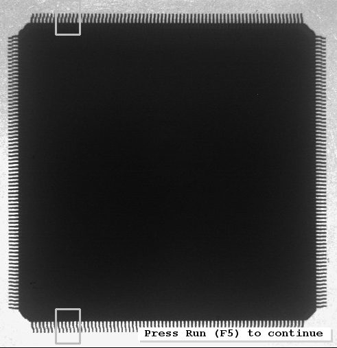
如图所示有两个 measure object
通过translate_measure (MeasureHandle, RowBottom, Column) 可以只生成一个 measure rectangle 另一个用该函数重新利用
Use an Absolute Gray Value Threshold
As an alternative to edge extraction, the measurements can be performed based on an absolute gray value
threshold by using the operator measure_thresh. Here, all positions where the gray value crosses the
given threshold are selected.
threshold by using the operator measure_thresh. Here, all positions where the gray value crosses the
given threshold are selected.
Fuzzy Measuring
In case there are extra edges that do not belong to the measurement, HALCON offers an extended
version of measuring: fuzzy measuring. This tool allows to define so-called fuzzy rules, which describe
the features of good edges. Possible features are, e.g., the position, the distance, the gray values, or the
amplitude of edges. These functions are created with create_funct_1d_pairs and passed to the tool
with set_fuzzy_measure. Based on these rules, the tool will select the most appropriate edges.
The advantage of this approach is the flexibility to deal with extra edges even if a very low min-
imum threshold or smoothing is used. An example for this approach is the example program
fuzzy_measure_pin.hdev on page 53.
Please refer to the Solution Guide III-A, chapter 4 on page 33, for more information.
Evaluation of Gray Values
To have full control over the evaluation of the gray values along the measurement line or arc, you can use
measure_projection. The operator returns the projected gray values as an array of numbers, which
can then be further processed with HALCON operators for tuple or function processing (see the chapters
“Tuple” and “Tools . Function” in the Reference Manual). Please refer to the Solution Guide III-A,
section 3.4 on page 22, for more information.
本文出自勇哥的网站《少有人走的路》wwww.skcircle.com,转载请注明出处!讨论可扫码加群:


")
")
常用的6种方法")
 封装运动功能")


Qt Widgets Designer界面设计器和界面应用")
:if的bool判断, 变量的作用域范围, 格式字符串, 弹窗, 列表推导式, 一个点歌小程序")